-
Products related to categories: servo, frequency conversion, HMI, driver, distributed DCS, IPC (PC bus industrial computer), PLC (programmable control system), DCS (distributed control system), FCS (field bus system), robot and other products and technical services.
-
Applications: Wind energy, automobile, ship, transportation, manufacturing, aviation, petroleum, natural gas, thermal power, thermal power, nuclear energy, steel, metallurgy, mining, power and other industries
-
Controller PLC\Robot servo drive Electro-hydraulic servo valve\DCS system/Distributed control systemSystem rack\Communication adapter\Analog output\Analog input\
-
\Multi-meter energy meter\Ignition\circuit board\Crimp terminal\Electric ac drive\Low voltage DC power module\Electro-hydraulic\servo valve\Automatic control system\exchange\Network communication module
controller\Processor module\dynamo\Electric machine\Servo drive\Touch screen\Input/output module\Water treatment monitoring system\Automobile\manufacturing system\Thermoelectric control system\ -
Digital output\Digital input\Mechanical protection system\High speed CPU
-
Electric power system\Chemical testing system\Petroleum control system\Tension monitoring system
-
DCS Distributed\control system\Steel control system\Steam\turbine system\Power generation system\
-
Thermal power generation system\Wind power system\Medium and high voltage frequency\conversion system\Precision motion system\Programmable control system\
-
Singapore New Energy Corporation
-
Geylang Bahru Industrial Estate
-
การทางหลวงแห่งประเทศไทย
-
American Petroleum Group
-
Indian shipping works
-
Pakistan Gas Company
-
Russian Automotive Industry Corporation
-
Brazilian Mining Company
-
Bangladesh Hydro power Plant
-
Egyptian Iron and Steel Manufacturing Co
-
Groupe d’exploitation du métro français
-
Für meinen vater
-
Mongolia Wind Farm
-
Empresa venezolana de procesamiento de petróleo
-
alibaba
-
Sichuan Huayingshan Power Plant
-
Huadian Datong Power Plant
-
Guodian Shuangyashan Power Generation Co., Ltd.
-
Baosteel Group Xinjiang Bayi Steel Co., Ltd.
-
Guodian Changzhou Power Plant
-
Xingtai Iron and Steel Co., Ltd.
-
Guodian Fee County Power Generation Co., Ltd.
-
Yangzhou Second Power Plant
-
Sichuan Jintang Power Plant
-
Xingcheng Special Steel Co., Ltd.
-
Quzhou Yuanli Metal Products Co., Ltd.
-
Zijin Mining Group
-
(Bangladesh) Metro Construction Company
-
WuHan steel co., ltd.
-
MaAnShan steel co., ltd.
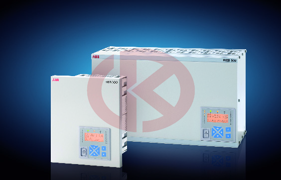
ABB Distributed busbar protection REB500
ABB Distributed busbar protection REB500
Main features
• Low-impedance busbar protection
• Stub and T-zone protection
• High functional reliability due to two independent
measurement criteria:
- stabilized differential current algorithm
- directional current comparison algorithm
• Phase-by-phase measurement
• Reduced CT performance requirements
• High through-fault stability even in case of
CT saturation
• Full solid-state busbar replica
• No switching of CT circuits
• Only one hardware version for
- 1 and 5 A rated currents
- all auxiliary supply voltages between
48 V DC an
Bay unit (500BU03)
The bay unit (see Fig. 4) is the interface
between the protection and the primary system
process comprising the main CTs, isolators
and circuit-breaker and performs the
associated data acquisition, pre-processing,
control functions and bay level protection
functions. It also provides the electrical insulation
between the primary system and the
internal electronics of the protection.
The input transformer module contains four
input CTs for measuring phase and neutral
currents with terminals for 1 A and 5 A. Additional
interposing CTs are not required,
because any differences between the CT
ratios are compensated by appropriately configuring
the software of the respective bay
units.
Optional input transformer module also contains
five input voltage transformers for the
measurement of the three-phase voltages and
two busbar voltages and recording of voltage
disturbances or 6 current transformers for
transformer differential protection. (see
Fig. 12).
In the analog input and processing module,
the analog current and voltage signals are
converted to numerical signals at a sampling
rate of 48 samples per period and then
numerically preprocessed and filtered accordingly.
Zero-sequence voltage and zero-current
signals are also calculated internally. The Process
d 250 V DC
- nominal frequencies of 50, 60 and
16.7 Hz
• Short tripping times independent of the
plant’s size or configuration
• Centralized layout: Installation of hardware
in one or several cubicles
• Distributed layout: Bay units distributed
and, in the case of location close to the
feeders, with short connections to CTs, isolators,
circuit breakers, etc.
• Connections between bay units and central
unit by fiber-optic cables
- maximum permissible length 1200 m
- for distributed and centralized layout
• fiber-optic connections mean interferenceproof
data transfer even close to HV power
cables
• Replacement of existing busbar protection
schemes can be accomplished without restrictions
(centralized layout) in the case of
substation extensions e.g. by a mixture of
centralized and distributed layout
• Easily extensible
• User-friendly, PC-based human machine
interface (HMI)
• Fully numerical signal processing
• Comprehensive self-supervision
• Binary logic and timer in the bay unit
• Integrated event recording
• Integrated disturbance recording for power
system currents
• A minimum of spare parts needed due to
standardization and a low number of varying
units
• Communication facilities for substation
monitoring and control systems via
IEC 61850-8-1, IEC 60870-5-103 and LON
• IEC 62439 standard redundant station bus
communication
• IEC 61850-9-2 LE process bus communication
• Cyber security to support
- User Access Management
- User Activity Logging
Options
• Breaker failure protection (also separately
operable without busbar protection)
• End fault protection
• Definite time overcurrent protection
• Breaker pole discrepancy
• Current and voltage release criteria
• Disturbance recording for power system
voltages
• Separate I0 measurement for impedancegrounded
networks
• Communication with substation monitoring
and control system (IEC 61850-8-1 /
IEC 60870-5-103 / LON)
• Internal user-friendly human machine interface
with display
• Redundant power supply for central units
and/or bay units
REB500
The numerical busbar protection REB500 is
designed for the high-speed, selective protection
of MV, HV and EHV busbar installations
at a nominal frequency of 50, 60 and 16.7 Hz.
The structure of both hardware and software
is modular enabling the protection to be easily
configured to suit the layout of the primary
system.
The flexibility of the system enables all configurations
of busbars from single busbars to
quadruple busbars with transfer buses, ring
busbars and 1½ breaker schemes to be protected.
In 1½ breaker schemes the busbars and the
entire diameters, including Stub/T-Zone can
be protected. An integrated tripping scheme
allows to save external logics as well as wiring.
The capacity is sufficient for up to 60 feeders
(bay units) and a total of 32 busbar zones.
The numerical busbar protection REB500
detects all phase and earth faults in solidly
grounded and resistive-grounded power systems
and phase faults in ungrounded systems
and systems with Petersen coils.
The main CTs supplying the currents to the
busbar protection have to fulfil only modest
performance requirements (see page 18). The
protection operates discriminatively for all
faults inside the zone of protection and
remains reliably stable for all faults outside the
zone of protection.
REB500sys
The REB500sys is foreseen in MV, HV and
EHV substations with nominal frequencies of
16.7, 50 Hz or 60 Hz to protect the busbars
and their feeders. The bay protection functions
included in REB500sys are used as
Main 2 / Group 1 - or back-up protection.
The system REB500sys is foreseen for all single
or double busbar configurations (Line variants
L-V1 to L-V7 and Transformer variant TV1
to T-V4). In 1½ breaker configurations,
variant L-V5 can be used for the bay level
functions autoreclosure and synchrocheck.
The capacity is sufficient for up to 60 feeders
(bay units) and a total of 32 busbar zones.
The REB500sys detects all bus faults in solidly
and low resistive-grounded power systems,
all kind of phase faults in ungrounded
and compensated power systems as well as
feeder faults in solidly, low resistive-grounded,
compensated and ungrounded power systems.
The protection operates selectively for all
faults inside the zone of protection and
remains reliably stable for all faults outside the
zone of protection.
REB500sys is perfectly suited for retrofit concepts
and stepwise upgrades. The bay unit is
used as a stand-alone unit for bay protection
functions (e.g. line protection, autoreclosure
and synchrocheck or 2- and 3 winding transformer
protection or autonomous T-zone protection).
The central unit can be added at a
later stage for full busbar and breaker failure
protection functionality.
data are transferred at regular intervals
from the bay units to the central processing
unit via the process bus.
Every bay unit has 20 binary inputs and 16
relay outputs. The binary I/O module detects
and processes the positions of isolators and
couplers, blocking signals, starting signals,
external resetting signals, etc. The binary
input channels operate according to a patented
pulse modulation principle in a nominal
range of 48 to 250 V DC. The PC-based HMI
program provides settings for the threshold
voltage of the binary inputs. All the binary output
channels are equipped with fast operating
relays and can be used for either signaling or
tripping purposes (see contact data in Table
8).
A software logic enables the input and output
channels to be assigned to the various functions.
A time stamp is attached to all the data
such as currents, voltages, binary inputs,
events and diagnostic information acquired by
a bay unit.
Where more binary and analog inputs are
needed, several bay units can be combined to
form a feeder/bus coupler bay (e.g. a bus coupler
bay with CTs on both sides of the bus-tie
breaker requires two bay units).
The bay unit is provided with local intelligence
and performs local protection (e.g. breaker
failure, end fault, breaker pole discrepancy),
bay protection (Main 2 or back-up bay protections)
as well as the event and disturbance
recording.
High-speed distance protection
• Overcurrent or underimpedance starters
with polygonal characteristic
• Five distance zones (polygon for forwards
and reverse measurement)
• Load-compensated measurement
• Definite time overcurrent back-up protection
(short-zone protection)
• System logic
- switch-onto-fault
- overreach zone
• Voltage transformer circuit supervision
• Power swing blocking function
• HF teleprotection. The carrier-aided
schemes include:
- permissive underreaching transfer tripping
- permissive overreaching transfer tripping
- blocking scheme with echo and transient
blocking functions
• Load-compensated measurement
- fixed reactance slope
- reactance slope dependent on load
value and direction (ZHV<)
• Parallel line compensation
• Phase-selective tripping for single and
three-pole autoreclosure
• Four independent, user-selectable setting
groups.
In the supervision mode the active and reactive
power with the respective energy direction
is displayed by the HMI500.
Autoreclosure
The autoreclosure function permits up to four
three-phase autoreclosure cycles. The first
cycle can be single phase or three-phase.
If the REB500sys autoreclosure function is
employed, it can be used as a back-up for the
autoreclosure realized externally (separate
equipment or in the Main 1 protection).
When the autoreclosure function is realized
outside of REB500sys, all input and output
signals required by the external autoreclosure
equipment are available in order to guarantee
correct functionality.
Synchrocheck
The synchrocheck function determines the difference
between the amplitudes, phase
angles and frequencies of two voltage vectors.
The synchrocheck function also contains
checks for dead line and dead bus.
Transformer differential protection
• For two- and three-winding transformers
• Auto transformers
• Three-phase function
• Current-adaptive characteristic
• High stability for external faults and current
transformer saturation
• No auxiliary transformers necessary
because of vector group and CT ratio compensation
• Inrush restraint using 2nd harmonic
The transformer differential protection function
can also be used as an autonomous T-zone
protection in a 1½ breaker scheme.
Thermal overload
This function protects the insulation against
thermal stress. This protection function is normally
equipped with two independently set
levels and is used when oil overtemperature
detectors are not installed.
Peak value over- and undercurrent protection
These functions are used for current monitoring
with instantaneous response and where
insensitivity to frequency is required.
Peak value over- and undervoltage protection
This function is used for voltage monitoring
with instantaneous response and where insensitivity
to frequency is required.
Frequency function
The function is used either as an over-/ underfrequency
protection, or for load-shedding in
the event of an overload. Several stages of
the frequency protection are often needed.
This can be achieved by configuring the frequency
function several times.
Rate of change frequency protection df/dt
This function is used for the static, dynamic
and adaptive load-shedding in power utilities
and industrial distribution systems. The function
supervises the rate-of-change df/dt of one
voltage input channel. Several stages of the
rate-of-change frequency protection are often
needed. This can be achieved by configuring
the rate-of-change frequency function several
times.
Definite time overfluxing protection
This function is primarily intended to protect
the iron cores of transformers against excessive
flux. The function works with a definite
time delay. The magnetic flux is not measured
directly. Instead the voltage/frequency-ratio,
which is proportional to the flux is monitored.
Inverse time overfluxing protection
This function is primarily intended to protect
the iron cores of transformer against excessive
flux. The function works with an inverse
time delay. The inverse curve ca be set by a
table of 10 values and the times t-min and tmax.
The magnetic flux is not measured directly.
Instead the voltage/frequency-ratio,
which is proportional to the flux is monitored.
Power function
This function provides single, or three phase
measurement of the real or apparent power.
The function can be configured for monitoring
reverse, active or reactive power (power
direction setting). Phase angle errors of the
CT/VT inputs can be compensated by setting.
The operating mode can be configured either
to underpower or to overpower protection.
Logics and delay/integrator
These functions allow the user the engineering
of some easily programmable logical functions
and are available as standard also in the
REB500 functionality.
Directional sensitive earth fault protection
for grounded systems
A sensitive directional ground fault function
based on the measurement of neutral current
and voltage is provided for the detection of
high-resistance ground faults in solidly or lowresistance
grounded systems. The scheme
operates either in a permissive or blocking
mode and can be used in conjunction with an
inverse time earth fault overcurrent function.
In both cases the neutral current and voltage
can be derived either externally or internally.
This function works either with the same communication
channel as the distance protection
scheme or with an independent channel.
Directional sensitive earth fault protection
for ungrounded or compensated systems
The sensitive earth fault protection function for
ungrounded systems and compensated systems
with Petersen coils can be set for either
forwards or reverse measurement. The characteristic
angle is set to ±90°
(U0 · I0 · sin ) in ungrounded systems and to
0° or 180° (U0 · I0 · cos ) for systems with
Petersen coils. The neutral current is always
used for measurement in the case of systems
with Petersen coils, but in ungrounded systems
its use is determined by the value of the
capacitive current and measurement is performed
by a measuring CT to achieve the
required sensitivity. To perform this function
the BU03 with 3I, 1MT and 5U is required.
Definite time over- and undercurrent protection
This function is used as Main 2 or as back-up
function respectively for line, transformer or
bus-tie bays. This function can be activated in
the phase- and/or the neutral current circuit.
Inverse time overcurrent protection
The operating time of the inverse time overcurrent
function reduces as the fault current
increases and it can therefore achieve shorter
operating times for fault locations closer to the
source. Four different characteristics according
to British Standard 142 designated normal
inverse, very inverse, extremely inverse and
long time inverse but with an extended setting
range are provided. The function can be configured
for single phase measurement or a
combined three-phase measurement with
detection of the highest phase current.
Inverse time earth fault overcurrent protection
The inverse time earth fault overcurrent function
monitors the neutral current of the system.
Four different characteristics according
to British Standard 142 designated normal
inverse, very inverse, extremely inverse and
long time inverse but with an extended setting
range are provided.
Directional overcurrent definite / inverse
time protection
The directional overcurrent definite time function
is available either with inverse time or definite
time overcurrent characteristic. This
function comprises a voltage memory for
faults close to the relay location. The function
response after the memory time has elapsed
can be selected (trip or block).
Definite time over- and undervoltage protection
This function works with a definite time delay
with either single or three-phase measurement.
- AEROTECH
- MOOG
- ABB
- HIMA
- GE
- Prosoft
- EMESRON
- EPRO
- rockwell
- Technical Data
- Product Information
- Industry Information
- Company News
- DEIF
- Triconex
- UNIOP
- REXROTH
- Woodward
- Lumentum
- Honeywell
- National Instruments
- Bently Nevada
- MOTOROLA
- FOXBORO
- Enterasys
- KOLLMORGEN
- SIEMENS
- SST
- YOKOGAWA
- sieger
- RELIANCE
- meggitt
- VMIC
- ALSTOM
- EATON
- METSO
- Abaco
- HIRSCHMANN
- Rolls-Royce
- BENDER
- AMAT
- Brand
- ORMEC
- WATLOW
- Schneider
- PRAXIS-Automation
- BASLER
- Kongsberg
- DISCO Corporation
-
BASLER DECS-250-CN1SN1N Digital Excitation Control System DECS250CN1SN1N
-
GE IS420ESWAH3A 8-port 10/100 base copper only
-
IS420ESWAH1A 8-port 10/100 base copper with one 100 Mbps
-
GE IS420ESWAH2A 8-port 10/100 base copper
-
GE IS420ESWBH1A 16-port 10/100 base copper with
-
GE PQMII-T20-C-A Power Quality Meter
-
GE Mark VI IS230PCAAH1A/B Combination module unit
-
ABB 3BHE021887R0101 UBCC717BE101 Board 3BHB002751R0102
-
ABB 3BHE032593R0001 Isolated Power Supply
-
ABB 3BSC610023R0001 POWER SUPPLY SD812
-
Sleeve matching ABB PFSC230 3BSE081054R1, 25M
-
ALSTOM 029.204431 Power unit module Accessory Mainboard
-
ALSTOM Converteam 029.302250 Power unit module
-
GE IS420UCSBH1A Mark Vle UCSC Controller
-
GE EX2100e Power Conversion Module 151X1235DB15SA1
-
MOOG G122‑829A P-I SERVO AMPLIFIER
-
S-D4017 Remote IO Backplane SSBP-1 RELIANCE drive module
-
CC-link card CCLK-1 S-D4030 RELIANCE drive module
-
Digital IO card DIO-1 S-D4006 RELIANCE drive module
-
S-D4041 DSPM-2A DSP RELIANCE drive module
-
abb 3BUS208720-001 POWER SIGNAL INTERCONNECT
-
GE DS3800NB1A Control Drive Board Serial Port Terminal Board
-
ABB EI813F 3BDH000022R1 communication card
-
TMEIC KPAD-3122A A3XAP02 LCD Display With Key Drive Accessories
-
ALSTOM F425368001 Rupture Disc 110 kV Gas Insulated Switchgear
-
80190-219-01G Allen Bradley Driver Pcb Board IGCT
-
GE DS3815PAHB1A Control Unit Drive Board
-
GE Mark VI IS230JPDGH1B Combination module unit
-
ABB 1MRK002247-Apr04 I/O-modules 670 series
-
ABB 0769143 A CELL SAMPLE AL175MM Gas analyzer accessories
-
RS NX700 Series Controller OEMAX SAMSUNG NX-Y64T
-
RS NX700 Series Controller OEMAX SAMSUNG NX-Y32T
-
NX700 Series Controller OEMAX SAMSUNG NX-X64D 64 output
-
NX-X32D 32 output Series Controller OEMAX
-
NX700 Series Controller OEMAX SAMSUNG NX-POSI4
-
NX-MWLINK Series Controller OEMAX SAMSUNG
-
RS NX-ETHERNET Series Controller OEMAX SAMSUNG
-
NX700 Series Controller OEMAX SAMSUNG NX-DEVICE
-
a-b NX700 Series Controller OEMAX SAMSUNG NX-CPU760C
-
NX700 Series Controller OEMAX SAMSUNG NX-BASE12
-
RS NX700 Series Controller OEMAX SAMSUNG NX-AO4V
-
NX700 Series Controller OEMAX SAMSUNG NX-AI8V
-
PowerFlex® 7000 ForGe Drives which utilize the new HMI Interface Board 80190-780-01-R
-
GCU-08 CB-130 80173-109-01-3 Mitsubishi Thyristor Inverter Power Board
-
a-b 1769-L30 CompactLogix 5370 L3 Controllers
-
A-B MicroLogix™ 1762-OW16 Relay Output Module
-
A-B 1761-ENT-AIC advanced interface converter
-
1761-CBC-PM02 ControlLogix Redundancy System cable
-
A-B 1746-IV16 16DI 10-30V DC SOURCE MODULE SLC 16 Digital Inputs
-
A-B 1746-IB16 module Rockwell SLC 16-point digital input control
-
A-B 1734-MB Memory system memory card
-
A-B 1336-BDB-SP4D 74103-244-54 1336 PLUS II Servo drive power board
-
RELIANCE 0-60067-1 0-60067 Automax Drive Board 0-60067-A
-
RELIANCE 0-60066-1 0-60066 S0-60066 Automax Drive Board
-
Meggitt C327845-11 Flow shutoff valve -7 -5 Parker
-
Driver board 029.204 686 Alstom power unit
-
ABB 3BSE020828R1 DSAI130DK01 Combined analog input module
-
ABB SCC-C 23070-0-101142100000 Continuous Emission Monitoring System (CEMS) Sample gas cooler
-
Siemens 6SE7038-6EK84-1JC2 Inverter Gate Triggering IGD8
-
GE IS200AEPBH1BBA Fan power generation power board
-
ALSTOOM MVS3000-4001 Handheld controller unit
-
PILZ 630613 PSEN OP 4H-S-30-060 Light Curtain Receiver
-
schneider SQUARE D POWERLOGIC CM4250 CIRCUIT MONITOR 96ma
-
EATON E84BAN Crane Control Heavy Duty Mill Limit Switch 2200 VAC 2NO-1NC Contact
-
MVI56 PDP-MV1 ALEN-BRADLEY PROSOFT PROFIBUS UNIT MVI56PDPMV1
-
ABB SCC-C Sample gas cooler 23070-0-10211110
-
GE PN.246B9953BPG1 TOOL-SCR REMOVAL
-
GUTOR BY SCHNEIDER ELECTRIC OP2446 MAIN PROCESSOR BOARD
-
HONEYWELL FX-USI-0002 Universal Safety Interface Module
-
HONEYWELL TA3840S Communication Unit
-
ABB 19P123085397 PDD AVR Unit
-
EMERSON 5X00899G01 Ovation™ Power Supply System
-
ABB 5SHY3545L0020 3BHE014105R0001 5SXE05-0154 IGCT Module
-
4TB5203-0402 Liquid crystal display panel
-
ABB 3BHE036348R0101 Expansion bracket card
-
ABB 3BHE017400R0101 PPD104 Extended memory card
-
ABB 3BHE012049R0001 Fiber Optic Expansion Motherboard
-
ABB 3BHE006805R0001 High Voltage Inverter Motherboard
-
ABB 3BHE000412R0101 INU INTERFACE BOARD
-
ABB UCD208A101 3BHE020018R0101 control board card
-
ABB 3ADT309600R0012 SDCS-CON-2 Terminal UNIT
-
80190-480-01-R Allen Bradley Driver Pcb Board
-
ABB DSMB179 57360001-MS MEMORYBOARD
-
ABB DSMB178 57360001-MM MEMORYBOARD CATALOG DESCRIPTION
-
ALSTOM C264MB1D69500130A300000C000N10 micom C264 ds agile bay controller
-
ABB PFSK138 3BSE014292R1 Channel Control Unit PFSK 138
-
GE ALSTOM 029.380 896 Board Logical control 029380896
-
ABB S-123H 3BHB030479R0112 Power unit ACS 6000 System
-
GE PLB029-376433 Phase-controlled control module of gas compression unit
-
GE IGBT ProX690-1E1-0L0H1 Phase-controlled control module of gas compression unit PLB029-370338
-
GE Industrial System Mark V Display MMI 323A2374P2
-
VMEBUS RACK VME32 BACKPLANE 100-240V/50-60 Hz/1200W
-
IBA ibaLink-SM-128V-i-2oVMEbus Interface Board SM128V
-
VMIC VME-PMC-CADDY VME-Carrier Board for 2 PMC Modules
-
ABB REF620E_1G Feeder Protection and Control
-
ABB SACO16D1 Digital Annunciator Unit
-
ABB REF620 HBFNACNNNEA1BNN11G Feeder Protection and Control
-
GE UT150-2 CPU MODULE CARD FOR CE2000 CONTROLLER
-
ALSTOM TANSFORMER MAINTENANCE KIT 1000KVA UTHC GEC
-
ABB DASD146 3ASC25H270 Lifter controller accessories DASD145
-
ABB DASD147 3ASC25H280 Lifter controller accessories DASD107
-
ABB SCC-K Converter NO2/NO converter and Thermal converter 3KXG801000U0100
-
Siemens 6AV6643-0CD01-1AX1 SIMATIC MP 277 10" Touch
-
ABB UAC095AE01 HIEE300788R0001 Communication Control IO Board
-
ABB AC800PEC Measuring Interface PECMIUAD140 PECMI UA D140
-
ABB 500PSM03 1MRB150038 Power Supply module
-
Valmet metso D201563L Control unit accessories
-
Valmet metso D201473L AII8 Control unit accessories
-
EATON XVS-430-10MPI-1-10 Touch panel 24 V DC TFTcolor, ethernet, RS232
-
bently 60M100-00 Condition Monitoring System
-
ABB 3BHB004791R0101 IGCT Gate Power Supply Unit
-
ABB TAS.580.0550.G00 HARDWARE BOARD ABB100 COMPONENTS SIDE
-
ABB SYN5201A-Z,V277 3BHB006714R0277 Automatic single-channel synchronization unit
-
ABB SUE3000 1VCF750090R0804 Operation screen unit 1VCR007346
-
ABB SENSYCAL FCU400-IR Product Summary
-
ABB SDCS-CON-2-COAAT 3ADT220090R2 DCS Thyristor Power Converters accessories
-
ABB SCYC51220 63901075c Control Module
-
Siemens SYNCHRONOUS SERVOMOTOR 1FK6084-6AZ21-9ZZ9-Z S05
-
Siemens SYNCHRONOUS SERVOMOTOR 1FK6063-6AF71-1EH0
-
FOXBORO FBM241/b/c/d Discrete I/O Interface Modules
-
FOXBORO FBM242, Externally Sourced, Discrete Output Interface Module
-
FOXBORO FBM244, 0 to 20 mA I/O Interface Module with HART Support
-
FOXBORO FBM245, 0 to 20 mA I/O Interface Module with HART Support
-
FOXBORO FBM247, Current/Voltage Analog/Digital/Pulse I/O Configurable Interface Module
-
FOXBORO FBM218 HART Communication Redundant Output Interface Module
-
FOXBORO FBM219 Discrete I/O Interface Module
-
FOXBORO FBM222, Redundant PROFIBUS Communication Interface Module
-
FOXBORO FBM227, 0 to 10 V dc, Contact/dc I/O Interface Module


All new products and surplus products of the industrial intelligence industry, as well as the discontinued products of the original manufacturers. We are not an authorized distributor or representative of any of the above manufacturers (except for brand authorization). The trademarks, brand names and brands appearing in this agreement are the property of their respective manufacturers.
COPYRIGHT© 2003-2026 Copyrighted

Phone(WeChat/Whatsapp)
+086-181 4410 0983
No 1134 Jimei North Road,
Hong Kong Office:
Guan Tang District, Hong Kong,
